
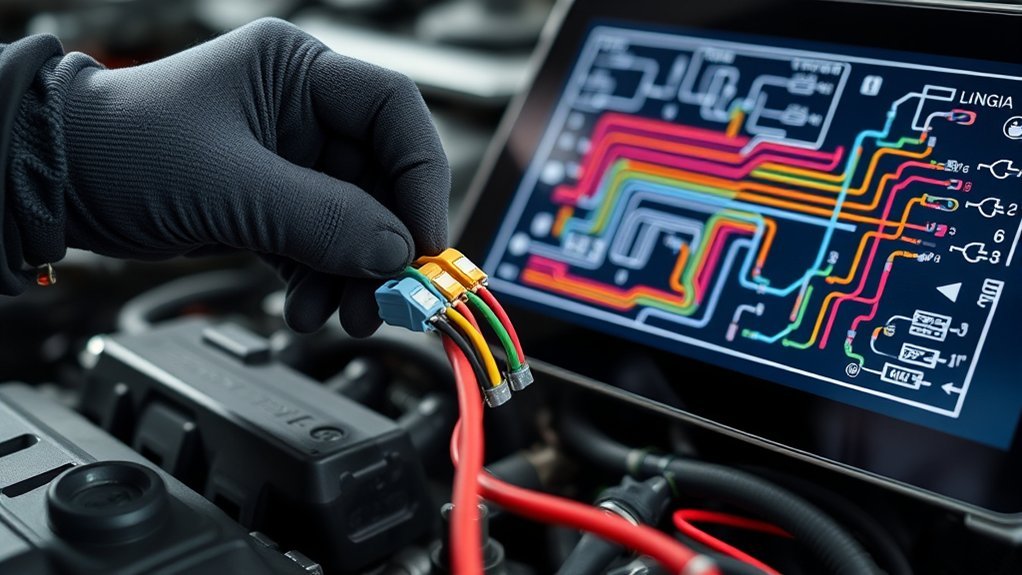
A 4-wire ignition coil diagram does not have one universal pinout. The connector has four terminals, but their jobs depend on the vehicle and coil design. Some systems use power, chassis ground, low reference, and an ECU control wire. Others use power, ground, a trigger signal, and an ignition-confirmation or feedback signal. Start with the correct wiring diagram, identify each terminal by function, and then test power, ground, control, and feedback in that order.
Quick Answer
To read a 4-wire ignition coil diagram, first identify the four terminals from the vehicle’s wiring diagram. Look for battery power, ground, the ECU trigger or ignition-control circuit, and either a low-reference or feedback circuit. Do not rely on wire color or assume every four-wire coil uses the same pinout.
Key Takeaways
- Four terminals do not mean four standardized functions; always check the vehicle wiring diagram.
- Most systems have a battery-voltage supply and at least one ground or reference circuit.
- The ECU trigger circuit controls when the coil charges and fires.
- Some systems use the fourth wire as an ECU low reference, while others use it as ignition-confirmation feedback.
- Do not use a universal 5 V, resistance, or pin-number specification unless the service information gives that value.
- Use a scope and current clamp when a basic power-and-ground test cannot explain the fault.
At a Glance
| Time Required | About 20–45 minutes for basic circuit checks |
| Difficulty | Intermediate automotive electrical diagnosis |
| Tools Needed | Vehicle wiring diagram, digital multimeter, back-probe leads, scan tool; oscilloscope and low-amp current clamp for advanced testing |
| Cost | Usually no parts cost for diagnosis if you already have the tools |
Warning: Ignition coils can generate tens of thousands of volts on the secondary side. Keep hands and unapproved test equipment away from energized spark-plug and high-voltage circuits. Turn the ignition off before unplugging or repairing connectors, and follow the vehicle manufacturer’s diagnostic procedure whenever live testing is required.
4-Wire Ignition Coil Pinout Basics
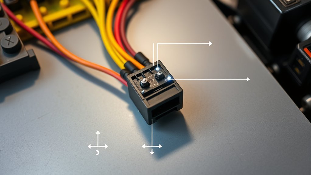
A 4-wire ignition coil normally contains an electronic switching circuit or works closely with the engine control module. The important point is that the four connector terminals are not standardized across every manufacturer.
For example, one vehicle may use battery power, chassis ground, an ECU low-reference circuit, and an ignition-control wire. Another may use battery power, ground, an ECU trigger signal, and an ignition-confirmation signal.
| Possible wire function | What it does |
|---|---|
| Battery or ignition power | Supplies the coil and its internal electronics |
| Ground | Provides the main electrical return path |
| ECU trigger / ignition control | Commands the coil to charge and fire |
| Low reference or feedback | May provide an ECU reference path or return an ignition-confirmation signal, depending on design |
Never assign a function from wire color alone. Find the connector end view and circuit diagram for the exact engine, note the terminal letters or numbers, and then match each terminal to its circuit name.
Identify Power, Ground, Signal, and Feedback
Start by separating the four circuits into roles. The power circuit supplies energy to the coil. The ground or low-reference circuits provide return paths. The trigger circuit tells the coil when to fire. A feedback circuit, when fitted, reports ignition activity back to the ECU.
The fourth terminal is where many generic diagrams become misleading. It may be a separate low-reference circuit on one engine and an ignition-confirmation circuit on another.
Power And Ground Pins
Locate the power pin from the wiring diagram. Many coil-on-plug systems receive switched battery voltage from a fuse or engine-control relay. With the ignition on, the supply should match the specification for that vehicle.
A voltage reading with the connector unplugged is only a first check. A corroded splice, weak relay contact, damaged terminal, or partly broken wire can still show battery voltage when no current is flowing. If the service procedure allows it, confirm that the supply remains healthy while the circuit is operating.
Next identify every return circuit separately. A terminal labeled Ground may connect to the engine or chassis, while a terminal labeled Low Reference may return to the ECU. Do not automatically join them together or assume they can be tested in exactly the same way.
With the ignition off and the system powered down, follow the manufacturer-specified resistance or continuity test. Some GM procedures, for example, specify a low-resistance path for both the ground and low-reference circuits on particular four-wire coil/module systems. That does not create a universal resistance specification for other vehicles.
Pro Tip: A voltage-drop test under load can reveal a weak power or ground connection that looks normal during an unloaded resistance test. Compare the suspect cylinder with a known-good cylinder whenever the wiring layout is the same.
Signal And Diagnostic Line
The signal wire is normally the ECU’s command to the ignition coil or its internal igniter. It controls dwell and the moment primary current is switched off to create the spark.
Do not assume the command is always a 5 V pulse. Signal level, polarity, dwell strategy, and waveform shape depend on the system. Use the manufacturer’s waveform information or compare the suspect coil with another cylinder on the same engine.
Some four-wire Toyota-style coil-on-plug systems use an IGT ignition-trigger signal from the ECU and an IGF ignition-confirmation signal returning to the ECU. If the expected confirmation signal is missing, the ECU can recognize an ignition-circuit fault.
Other four-wire systems do not use that Toyota-style feedback arrangement at all. Their fourth terminal may instead be a low-reference circuit.
Trace the Coil Wiring to the PCM
Trace the coil wiring before measuring it. A wiring diagram normally shows the coil connector, fuse or relay, splice points, grounds, and ECU terminals.
- Find the ignition-coil connector on the schematic.
- Write down all four terminal numbers or letters.
- Identify the fused power supply.
- Identify chassis ground and any separate ECU low-reference circuit.
- Follow the trigger or ignition-control wire to the ECU.
- If a feedback circuit is shown, trace that wire back to its ECU terminal.
Do not probe an ECU wire simply because its color looks familiar. Wire colors can change between model years, engines, harness sections, and markets.
Once you have mapped the circuit, compare the physical connector with the connector-end view. This prevents a common mistake: looking at the connector from the wire side when the service information numbers it from the terminal side.
Verify the Low-Reference Ground
A low-reference circuit should only be treated as part of the ignition-coil test when the wiring diagram actually identifies one. It is not automatically the same as a second chassis ground.
On certain GM-style four-wire coil/module systems, the ECU uses separate ground and low-reference circuits. Service procedures for those systems may call for a low-resistance check between low reference and ground after the vehicle electronics have powered down.
The original idea that a low-reference ground should universally measure more than 50,000 ohms to chassis is not a valid general ignition-coil rule. Use the exact circuit test for your vehicle.
Low-Reference Ground Path
Follow the low-reference wire from the coil to the ECU on the schematic. Inspect every connector, splice, and terminal along the route.
A high-resistance connection can change the reference voltage seen by the coil electronics and ECU. Possible causes include corrosion, loose terminal tension, water intrusion, damaged wiring, or a partially backed-out terminal.
Do not repair a low-reference circuit by adding an extra chassis ground unless the manufacturer specifically calls for that repair. Doing so can change the intended current path and create new electrical problems.
Ground Resistance Check
For an ohmmeter test, switch the ignition off and allow the vehicle modules to power down as required by the service procedure. Disconnect the connector or module terminals specified in the instructions before checking resistance.
Resistance limits vary. A reading that is acceptable for one vehicle may fail another manufacturer’s procedure. The safest rule is simple: use the service-information limit rather than a generic number from an internet pinout.
Also remember that an ohmmeter uses very little current. A connection can pass a resistance test yet develop excessive voltage drop when the coil is operating. If the basic resistance test passes but the fault remains, test the circuit under load.
Scope The Ground Signal
An oscilloscope can reveal a ground or reference problem that appears only while the coil is charging. Back-probe the circuit only when the service method permits it and use a suitable ground reference for the scope.
Watch for voltage rise, noise, or an unstable reference during the charging event. Compare the suspect cylinder with another coil using the same circuit design.
Do not confuse this measurement with the ECU trigger waveform. Ground/reference voltage, trigger voltage, feedback voltage, and primary current are different measurements and answer different diagnostic questions.
- Check the correct circuit first.
- Use a known-good cylinder for comparison.
- Look for repeatable waveform differences.
- Confirm connector and harness condition before condemning the ECU.
Check Grounding Before You Test
Before advanced testing, inspect every ignition-coil connector and ground point that belongs to the circuit. Look for corrosion, loose eyelets, overheated terminals, damaged insulation, oil in the spark-plug well, water intrusion, and terminals pushed backward inside the connector.
Use the wiring diagram to distinguish the main ground from any ECU low reference. Test each according to its own specification.
If the ground path is poor, repair it before replacing the coil. A coil cannot charge correctly if its supply or return path cannot carry the required current.
Note: A good static voltage reading does not always prove that a power or ground circuit is healthy. Corrosion or a damaged conductor may only show its effect when current flows.
Use a Scan Tool and Scope
Start electronic diagnosis with a scan tool. Record stored, pending, and current trouble codes before clearing anything. Misfire codes such as P0301–P0308 can identify the affected cylinder, while P0351-series codes can point toward an ignition-control circuit on vehicles that support those diagnostics.
Check freeze-frame data and cylinder misfire counters if available. If one cylinder is clearly different, inspect that coil and its spark plug before moving into deeper circuit testing.
An oscilloscope becomes especially useful when power and ground pass basic tests but the coil still does not operate correctly.
- Check the ECU trigger waveform.
- Check feedback if the system provides it.
- Measure primary current on the correct current path.
- Compare the suspect cylinder with a known-good one.
- Repeat the test during the operating condition that causes the misfire.
A code does not automatically mean the coil itself has failed. An open wire, shorted control circuit, loose terminal, poor ground, damaged spark plug, or ECU driver problem can produce a similar symptom.
[Products Worth Considering]

The Tyre Glider is the original clip-on bicycle tyre lever designed to glide tyres on and off with controlled, effortless use. Its reinforced, glass-filled nylon construction helps it withstand high forces without snapping, while the smooth polymer surface protects rims and tubes. Universal compatibility makes it suitable for a wide range of tyres, including road, MTB, and gravel, for both tubed and tubeless setups.

Replace your worn or missing TPMS sensors with pre-programmed, direct-fit sensors for compatible Ford, Lincoln, and select Mazda models. Each sensor comes ready to activate with a scan tool, helping restore accurate tire pressure monitoring and trouble-free installation. Built with a long-life CR2032 battery and tested before factory release, this set provides dependable performance with a one-year warranty.

The Big Rig Defense Tire Thumper is a truck tire pressure checker that lets you quickly check multiple tires by giving them a firm whack. Listen for a reassuring thump and feel the stick bounce when a tire is fully inflated, helping you get back on the road safely. It features a comfortable, glove-friendly handle and a secure wrist strap for confident use on busy routes.
Measure Coil Command and Current
Trigger voltage and primary current are related, but they are not the same measurement.
The trigger signal tells the coil electronics when to act. Primary current shows whether the coil’s primary circuit actually draws and stores energy.
[Products Worth Considering]

Accurately measure tire tread depth with a calibrated gauge marked from 0 to 1 inch in 1/32 inch increments. The color-coded bar helps you quickly identify tread condition ranges, supporting safe driving for trucks, motorcycles, automobiles, and passenger vehicles.

Monitor tire tread wear with a smart, color-coded depth gauge that shows clear condition ranges at a glance. The bar is range marked for fast, easy readings, helping you maintain safer traction and performance. Each gauge is portable with a pocket clip, and the set includes 20 units for daily use and sharing.
This universal magnetic jack pad is designed to protect pinch welds when lifting vehicles, helping prevent seam damage or warping. Crafted from solid aluminum with a nylon pad insert, it provides reinforced structural support and a secure fit for most single-vehicle pinch welds. Slotted for strong magnet holding, it supports safe jacking for cars, SUVs, trucks, and more.
Command Pulse Check
Use the wiring diagram to identify the coil command or trigger wire. Back-probe it with an oscilloscope using the test setup recommended for the vehicle.
Do not begin with the assumption that the signal must be exactly 5 V. Instead, check:
- Whether a repeating trigger is present.
- Whether the pulse occurs at the correct time.
- Whether the waveform is stable.
- Whether the suspect cylinder matches a known-good cylinder.
- Whether the signal changes when the fault occurs.
If the ECU produces a normal trigger but the coil produces no useful primary current or spark, continue testing the coil supply, ground, coil itself, and secondary ignition components.
Current Clamp Reading
A current clamp measures the coil’s primary current without opening the circuit. Place it around the primary-current path identified by the wiring diagram.
Depending on the ignition design, that may be the coil’s power-supply wire or an externally switched ground path. Do not automatically clamp the small ECU trigger wire; on many smart coils that wire carries a logic signal, not the primary charging current.
Watch the current rise during dwell. Compare peak current, ramp shape, charging time, and repeatability with another coil using the same design.
If the suspect coil has a noticeably different current ramp, determine whether the difference follows the coil when it is moved to another cylinder. If it stays with the original cylinder, investigate the wiring, supply, ground, spark plug, or ECU control before replacing additional parts.
Scope Waveform Comparison
Waveform comparison is often more useful than relying on a generic voltage number.
| Measurement | What it tells you |
|---|---|
| Trigger waveform | Whether the ECU is commanding the coil |
| Feedback waveform | Whether a feedback-equipped system is reporting ignition activity |
| Primary current ramp | Whether the coil primary circuit is charging normally |
| Power voltage | Whether the coil has an adequate supply |
| Ground/reference voltage | Whether the return path remains stable under load |
Compare the same measurement across several cylinders. A repeated difference on one cylinder is usually more meaningful than comparing the waveform with a generic internet screenshot from a different engine.
Compare GM, Toyota, and Delphi Coils
The easiest way to understand why generic four-wire pinouts cause trouble is to compare common designs.
| System example | Possible four-wire arrangement | Diagnostic point |
|---|---|---|
| GM-style individual coil/module | Ignition voltage, ground, low reference, ignition-control circuit | Ground and low reference are separate circuit names; the ECU monitors the control circuit |
| Common Toyota COP with built-in igniter | Battery supply, ground, IGT trigger, IGF ignition-confirmation signal | IGT commands ignition; IGF reports confirmation back to the ECU |
| Delphi replacement coil applications | Depends on the OE system | Use the vehicle wiring diagram when the coil has three, four, five, or more wires |
These examples show why you should never identify a four-wire ignition coil simply as “power, ground, signal, and feedback” without checking the application.
The connector has four terminals; the wiring diagram tells you what those four terminals actually do.
[Products Worth Considering]
The Tymate TM12 RV TPMS delivers real-time tire pressure and temperature monitoring with a stable 433Hz display for safer long-distance driving. It supports simultaneous monitoring across vehicle and trailer zones, includes six alarm modes for pressure, temperature, leakage, battery, and signal loss, and features easy DIY installation with auto calibration. Power is supplied via USB-C charging or solar recharging, with a wide 0–144 PSI range and up to 50 ft signal coverage for RVs and towable trailers.

The Topeak SmartGauge D2 delivers precise digital tire pressure readings for bikes, motorcycles, and sports equipment up to 250 psi (17 bar). Its rotating SmartHead works with both Presta and Schrader valves, so you can check pressure quickly without adapters. The LCD display makes it easy to read results in psi, bar, or kg/cm² with an included CR2032 battery for immediate use.

This car D-wheel lock nut key provides an anti-theft solution for D-shaped wheel lock bolts, helping keep your wheels secure. It features a flower-shaped internal pattern that resists micro-adjustment theft while allowing removal and mounting of compatible locking nuts. Made for reliable performance under high torque, it’s easy to use with standard socket wrench turning for quick tire maintenance and emergency repairs.
Spot Common 4-Wire Wiring Faults
Many ignition-coil problems are caused by the circuit around the coil rather than the coil itself.
- Missing power: open fuse, relay problem, damaged splice, or broken supply wire.
- Weak ground: corrosion, loose fastener, damaged wire, or poor connector contact.
- Low-reference fault: open or high-resistance reference circuit on systems that use one.
- Control-circuit fault: open, short to ground, short to voltage, or poor terminal contact.
- Feedback fault: missing or corrupted confirmation signal on feedback-equipped systems.
- Connector damage: spread terminals, pushed-out pins, water intrusion, or heat damage.
- Harness damage: rubbing, vibration, previous repairs, or insulation melted against hot engine parts.
- Spark-plug-well contamination: engine oil or water can cause secondary ignition leakage and misfire.
If moving the suspect coil to another cylinder makes the misfire move with it, the coil becomes a strong suspect. If the misfire remains on the original cylinder, continue checking the spark plug, wiring, injector operation, compression, and other engine conditions.
Fix Coil Wiring Problems Safely
Turn the ignition off before unplugging the ignition coil or repairing the harness. If the repair procedure requires battery disconnection, follow the vehicle manufacturer’s instructions so retained settings, security systems, or module procedures are handled correctly.
Repair damaged wiring with the correct conductor size, terminals, seals, and approved splice method. Do not twist wires together and cover them with tape as a permanent engine-harness repair.
Make sure terminals lock into the connector body and cannot be pushed backward when the connector is installed. Re-secure the harness so it cannot rub against brackets, exhaust components, or sharp edges.
After the repair:
- Reconnect every ignition and engine connector.
- Verify power and ground again.
- Clear diagnostic codes if appropriate.
- Start the engine and check misfire data.
- Repeat the test under the conditions that originally caused the fault.
- Recheck for pending or returning DTCs.
Fast Diagnostic Sequence
If you need a simple order of operations, use this sequence:
- Confirm the correct diagram. Identify all four terminals.
- Scan for codes. Record misfire and ignition-control faults.
- Inspect the coil, plug, connector, and harness.
- Check coil power.
- Check ground and any low-reference circuit separately.
- Check the ECU trigger waveform.
- Check feedback if the system uses it.
- Measure primary current when needed.
- Compare with a known-good cylinder.
- Swap coils when appropriate. See whether the fault moves.
- Repair the circuit or replace the failed component only after the fault is isolated.
Frequently Asked Questions
How to Test a 4-Wire Ignition Coil With a Multimeter?
Start with the vehicle wiring diagram and identify power, ground, trigger, and any low-reference or feedback circuit. Use the multimeter to check the power supply and the ground or reference circuits according to the service specifications. Do not assume that measuring resistance across random coil terminals will test every modern smart coil. Some coil designs contain electronics or high-voltage diodes that change what resistance measurements are useful.
What Are the Four Wires on an Ignition Coil?
There is no universal four-wire arrangement. A common system may use battery power, ground, an ECU trigger, and feedback. Another may use battery power, chassis ground, an ECU low reference, and an ignition-control circuit. Identify the terminals from the wiring diagram for your exact vehicle.
How to Read an Ignition Coil Diagram?
Find the coil symbol and connector, note the pin numbers, and trace each wire outward. One should lead toward the ignition-power source, another toward ground or a reference circuit, and the control wires toward the ECU. Use circuit labels and connector numbers before relying on wire color.
Which Ignition Coil Is Number 4?
On an individual coil-on-plug system, ignition coil No. 4 normally corresponds to cylinder No. 4. That does not mean it is the fourth cylinder to fire. Cylinder numbering and firing order are different, so confirm cylinder locations and firing order in the engine service information.
Are 4-Wire Ignition Coil Wire Colors Universal?
No. Wire colors can vary by manufacturer, engine, model year, connector, and market. Always identify the circuit by pin number and wiring-diagram label before testing it.
Can a Bad Coil Ground Cause a Misfire?
Yes. A poor ground or high-resistance return path can interfere with coil charging or its internal electronics. However, test the exact ground and low-reference circuits shown in the vehicle diagram before adding grounds or replacing the coil.
Conclusion
A 4-wire ignition coil diagram becomes much easier to read once you stop assuming that every four-wire connector uses the same pinout. First identify each terminal from the vehicle wiring diagram. Then test the power supply, chassis ground, any separate low-reference circuit, the ECU trigger, and feedback if the system uses it.
Use a scan tool to identify the affected cylinder, a multimeter for basic circuit checks, and an oscilloscope or current clamp when you need to see what happens while the coil is operating. Most importantly, compare your readings with the manufacturer’s specifications or a known-good cylinder instead of relying on one universal voltage or resistance value.
Sources
- Delphi Technologies — ignition-coil service guidance explaining that multi-wire coils must be identified from the vehicle wiring diagram.
- HELLA TechWorld — ignition-coil operation, electrical testing, resistance-test limitations, oscilloscope diagnosis, and high-voltage safety guidance.
- Pico Technology Automotive — coil-on-plug trigger, primary-current, supply, ground, and waveform diagnostic procedures.
- Toyota repair information — IGT ignition-trigger and IGF ignition-confirmation circuit operation and waveform diagnosis.
- General Motors diagnostic information — ignition-control circuit monitoring and P0351-series diagnostics.
