
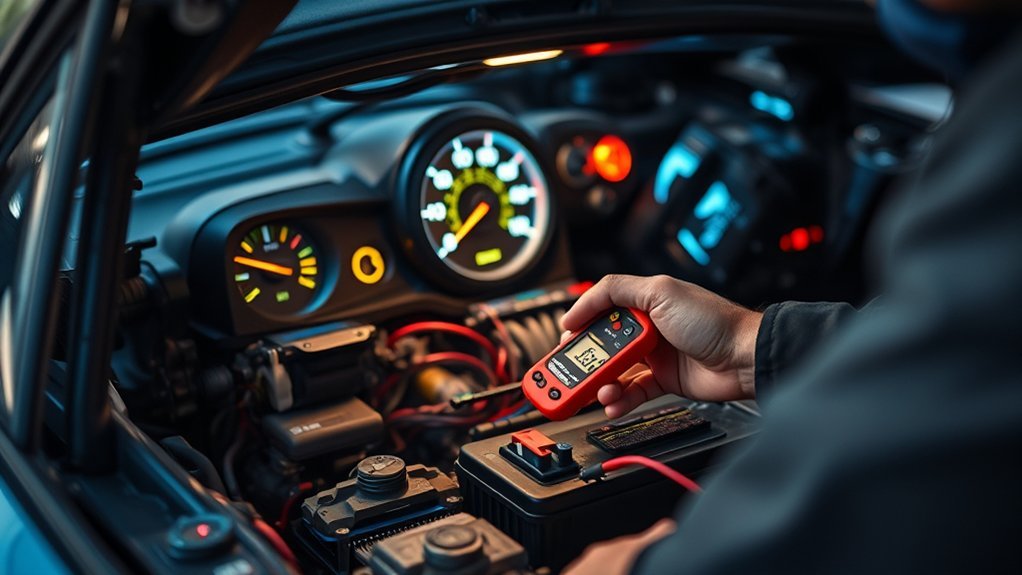
Your car’s electrical system starts the engine, powers lights and accessories, feeds sensors and control modules, and keeps the battery charged. In a conventional vehicle, a 12-volt battery supplies power before and during starting, while the charging system supports electrical loads after the engine runs. Fuses, relays, wiring, switches, grounds, and electronic modules control where that power goes and protect the circuits from faults.
Quick Answer
A car electrical system stores energy in the battery, uses that energy to operate the starter and electronics, and then replenishes the battery through the alternator or another charging device. Wiring and grounds complete each circuit, while fuses, relays, switches, sensors, and control modules distribute and manage electrical power.
Key Takeaways
- A conventional 12-volt battery supplies the high current needed for starting and powers electrical equipment when the engine is off.
- Once the engine is running, the alternator supplies electrical energy and recharges the battery. A general conventional-system test may show roughly 13–15 volts, but the correct value depends on the vehicle.
- Wiring carries current to each load, while ground wires and the metal body or engine can provide return paths to the battery.
- Fuses protect circuits against excessive current, while relays let a control circuit switch another circuit or load.
- Most individual vehicle loads are connected on parallel branches so they receive approximately the same system voltage and can operate independently.
- Some modern mild hybrids combine a conventional 12-volt system with a separate 48-volt electrical system.
What Does a Car Electrical System Do?
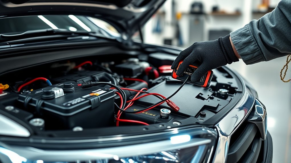
A car’s electrical system powers the starter motor, ignition or engine-management system, lights, sensors, infotainment equipment, pumps, motors, control modules, and many other components.
In a conventional gasoline or diesel vehicle, the battery stores electrical energy and supplies the large burst of current needed to crank the engine. It also supports electrical equipment when the engine is stopped and helps stabilize system voltage.
After the engine starts, the alternator converts mechanical energy from the engine into electrical energy. It supplies vehicle loads while restoring energy removed from the battery during starting.
Power then travels through wiring, connectors, switches, fuses, relays, electronic modules, and loads. The circuit must also have a return path to the battery. In most conventional vehicles, the negative battery terminal is connected to the body and engine, allowing metal parts of the vehicle to form part of the ground return network.
Fuses provide overcurrent protection. Eaton explains that a fuse is designed to interrupt an excessive-current condition such as an overload or short circuit before the fault can cause greater damage. Eaton’s fuse technology guide describes these overcurrent-protection principles.
Voltage drops, loose terminals, corrosion, damaged wires, weak batteries, poor grounds, failed charging components, and defective loads can all produce electrical symptoms. Depending on the affected circuit, you may notice dim lights, slow cranking, warning lamps, intermittent electronics, or a component that does not work at all.
Major Parts of a Car Electrical System
There is no universal rule saying every automotive electrical system has exactly five parts. A modern car may have hundreds of individual electrical and electronic devices. For a beginner, however, you can group the main functions like this:
| Part or Group | Main Job |
| Battery | Stores electrical energy and supplies starting and engine-off power. |
| Starter and starter control circuit | Uses high current to crank the engine on conventional starting systems. |
| Alternator or generator system | Produces electricity while the engine operates and replenishes the battery. |
| Fuses and circuit protection | Interrupt excessive current caused by overloads or faults. |
| Relays and switches | Turn circuits on and off or let one control circuit operate another circuit. |
| Wiring, connectors, and grounds | Carry current between the power source, controls, and loads and provide return paths. |
| Control modules and sensors | Measure conditions, exchange data, and electronically control vehicle functions. |
| Electrical loads | Use electrical energy to produce light, heat, motion, sound, computing, or another useful output. |
How the Car Electrical System Works
When you turn the key or press the start button in a conventional vehicle, the battery supplies power to the starting-control circuit. When the required conditions are met, the starter circuit energizes the starter motor, which turns the engine until it can run on its own.
The battery is commonly described as a 12-volt battery because 12 volts is the system’s nominal classification. Its actual terminal voltage changes with state of charge, temperature, load, battery chemistry, and operating conditions.
For a conventional lead-acid automotive battery, DENSO uses at least 12.6 volts as a fully charged open-circuit benchmark in its specified battery-testing procedure. That does not mean every reading below 12.6 volts proves the battery is bad. Proper testing may require charging, removing surface charge, checking the battery under load, and following the vehicle manufacturer’s procedure. See DENSO’s battery inspection and testing guidance.
After the engine starts, the alternator generates electrical energy and recharges the battery. DENSO gives 13 to 15 volts at the alternator and battery as a general charging-system test range at approximately 2,000 rpm, while also directing technicians to the vehicle service manual for the correct specification. See DENSO’s charging-system troubleshooting procedure.
Note: Do not assume every running car should always show the same charging voltage. Computer-controlled charging, start-stop systems, battery temperature, electrical demand, battery state of charge, and hybrid architecture can change how the charging system behaves. Use your vehicle’s service information when diagnosing it.
Most individual electrical loads are connected through parallel branches. This lets lights, sensors, motors, and other devices receive approximately the same system voltage while operating independently. The complete circuit may still contain series elements such as a fuse, switch, relay contact, connector, or ground connection.
Current, Voltage, Resistance, and Polarity
Understanding four basic terms makes automotive electrical diagrams much easier to read: voltage, current, resistance, and polarity.
| Term | Meaning |
| Current | The flow of electric charge, measured in amperes or amps (A). |
| Voltage | Electrical potential difference, measured in volts (V). |
| Resistance | Opposition to current flow, measured in ohms (Ω). |
| Polarity | The positive and negative orientation of a DC circuit. |
Voltage is often compared with pressure that pushes charge through a circuit, while current describes how much electric charge flows. Resistance limits that flow. Wire material, cross-sectional area, length, connectors, corrosion, and other circuit conditions all affect resistance.
NIST describes Ohm’s Law as the relationship between current, voltage, and resistance: I = V/R. You can also rearrange it as V = I × R. For example, one volt across one ohm produces one ampere of current in an ideal resistive circuit. You can review the relationship in NIST’s explanation of the ampere and Ohm’s Law.
Polarity also matters. Reversing battery or component connections can damage electronics, create sparks, or cause a circuit to operate incorrectly. Always verify terminal markings and the vehicle service procedure before disconnecting, testing, jump-starting, or reconnecting a battery.
How Fuses, Relays, and Wiring Protect Circuits
Even when system voltage is normal, current must reach each component through a circuit that is correctly sized and protected. Fuses, relays, connectors, and wiring each play a different role.
[Products Worth Considering]

ETENWOLF’s calibrated tire pressure gauge delivers accurate readings for cars, trucks, motorcycles, bikes, SUVs, RVs, and ATVs across a 0–75 PSI range. The large glow dial improves visibility in low light, while the 360° swivel chuck makes it easy to check valve pressure from any angle. It’s designed to stay accurate even in extreme hot or cold weather.
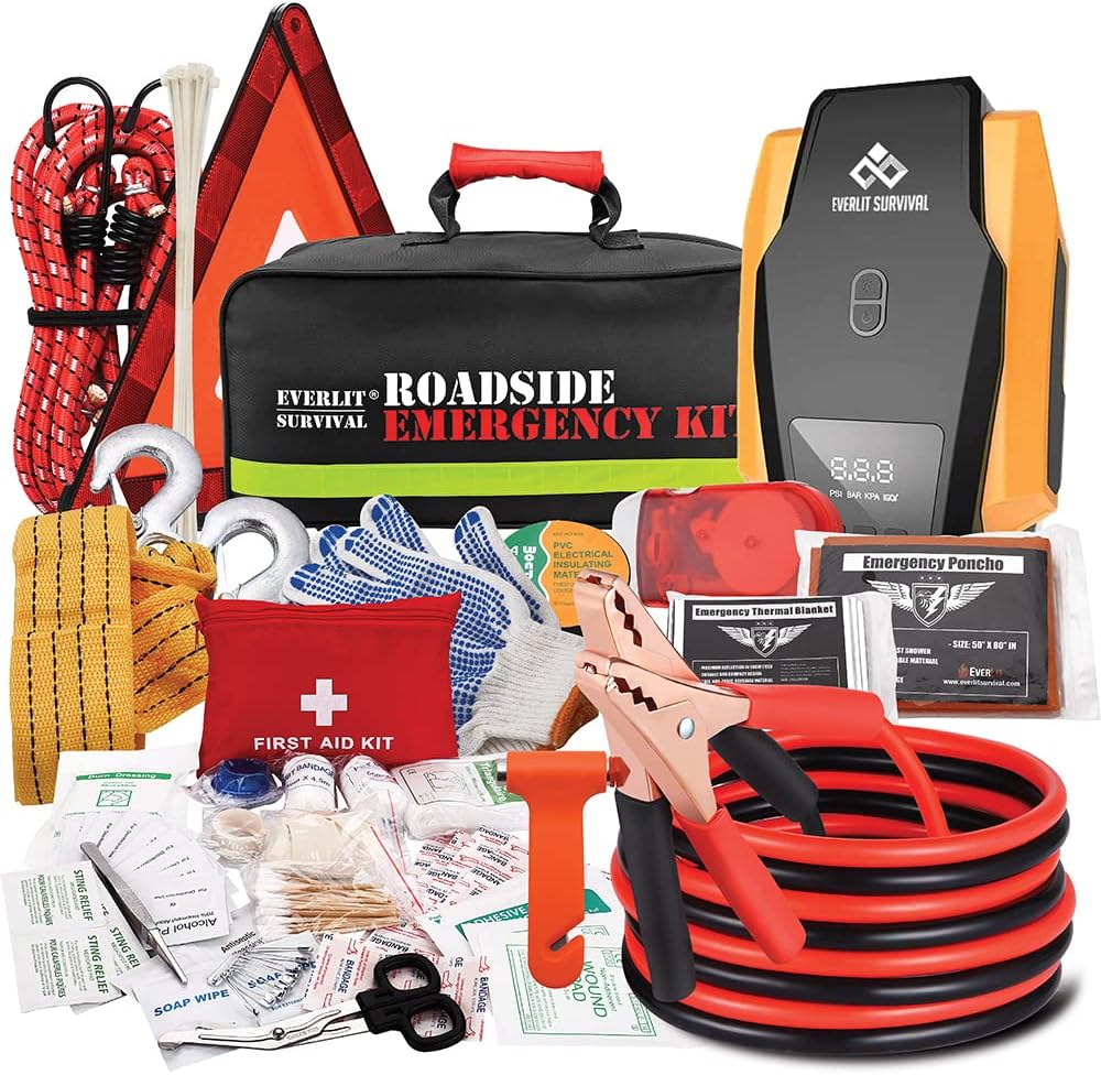
The Everlit Road Guardian emergency kit is designed for roadside breakdowns, combining essential safety gear and roadside tools in one compact bag. It includes a digital 12V auto tire inflator with preset and auto shutoff, plus 12-foot 8-gauge jumper cables to get you moving again. You also get a full 108-piece first aid kit, reflective warning tools, safety gloves, and emergency convenience items for safer travel.

Protect your Tesla during lifting with durable rubber jack pads designed to cushion pressure and help safeguard the battery and chassis. The non-slip, plug-and-play puck set fits Tesla Model 3/Y/X/S for safe, secure jacking. Each pack includes a portable storage case for cleaner trunk organization.
Fuses
A fuse is an overcurrent-protection device. If current rises sufficiently above the fuse’s design limits because of an overload or short circuit, the fuse element heats and opens the circuit. This helps isolate the fault and reduce the risk of wiring or component damage.
Warning: If a fuse blows repeatedly, do not install a higher-amperage fuse to stop it from opening. The repeated failure may indicate a short circuit, overloaded circuit, damaged component, or wiring problem. Use only the fuse type and rating specified for the vehicle.
Relays
A relay is an electrically operated switch. In a common electromechanical automotive relay, energizing a coil moves one or more contacts that open or close another circuit. This arrangement lets a control circuit operate a load circuit without requiring the dashboard switch or control module to carry the load current directly.
TE Connectivity’s automotive relay reference describes the coil-and-contact operating principle and common automotive relay arrangements.
Wiring and Connectors
Automotive wiring must be sized for the circuit’s expected current, length, temperature, installation environment, and acceptable voltage drop. An undersized, damaged, or corroded conductor can add resistance, creating excessive voltage drop and heat.
Manufacturers commonly use wire colors and tracers to help identify circuits, but automotive wire colors are not a universal code across every manufacturer and model. Use the correct wiring diagram instead of assuming that a certain color always performs the same function.
Series vs Parallel Circuits in Cars
Understanding series and parallel circuits helps you predict what should happen when a load, connection, or conductor fails.
Series Circuits
In a simple series circuit, electrical components are connected along one current path. The same current flows through every component. The individual resistances add together to form the total circuit resistance, while the source voltage is divided among the loads according to their resistance.
If the single current path opens—for example, because of a broken conductor or open switch—current stops throughout that series circuit.
Parallel Circuits
In a parallel circuit, each branch is connected across the same two electrical points, so each branch receives approximately the same supply voltage. Current divides among the branches according to their electrical characteristics.
This is why many automotive loads are arranged on parallel branches. A burned-out bulb on one properly designed branch does not normally stop another independent branch from operating.
Pro Tip: When troubleshooting a complicated wiring diagram, break it into smaller paths: power source, protection device, control device, load, and ground. Then test the circuit under the conditions in which the fault occurs.
Why Ground Connections Matter
A complete electrical circuit needs both a path from the power source to the load and a return path. In most conventional passenger vehicles, the negative battery terminal connects to the body and engine through heavy ground cables or straps. Many components use these structures as part of their return path, while other circuits use dedicated ground wires.
Corrosion, loose fasteners, damaged ground straps, contaminated mounting points, or damaged connectors can add resistance. That resistance creates a voltage drop when current flows.
DENSO recommends checking charging-system cables and connections and lists excessive voltage drop as an indication of poor connections or damaged cables. Its general charging-system procedure uses a maximum of about 0.2 volt on each side of the charging circuit, while the correct specification for a particular vehicle should come from its service information.
Ground faults can cause symptoms that appear unrelated, especially when multiple lights, sensors, motors, or modules share a ground point.
Common Car Electrical Problems and Symptoms
Electrical symptoms do not always identify the failed part by themselves. Use them as clues rather than replacing parts based on symptoms alone.
| Symptom | Possible Areas to Check |
| Slow or weak cranking | Battery state of charge and condition, battery terminals, starter cables, grounds, starter circuit, or starter motor. |
| No crank or only a click | Battery, terminals, starter relay/control circuit, neutral-safety or clutch input, starter solenoid, wiring, or starter. |
| Dim or flickering lights | Battery condition, charging system, loose connections, grounds, wiring resistance, or the lighting circuit itself. |
| Battery or charging warning light | Charging system, drive belt where applicable, alternator/generator control, wiring, battery connections, or related modules. |
| Fuse keeps blowing | Short circuit, overloaded circuit, damaged wiring, incorrect accessory installation, or a failed load. |
| Intermittent electrical failures | Loose terminals, corrosion, damaged connectors, broken conductors, grounds, relays, switches, or module/network faults. |
[Products Worth Considering]

The GOOLOO A3 3000A 12V jump starter delivers fast, reliable starts for dead vehicles while also providing a built-in 150 PSI cordless tire inflator. It supports gas and diesel engines up to 9.0L/6.5L and includes multiple inflation modes with smart shutoff and an LED display for convenient pressure control. A high-efficiency BMS provides 10 safety protections, and the unit also functions as a flashlight and device-charging power bank.

Steelman white tire marking crayons provide high-contrast, semi-permanent marks for repairing and inspecting tires and equipment. They write on wet or dry, smooth or coarse surfaces including rubber, metal, glass, and wood, making them ideal for puncture location and damage outlining. The lead- and zinc-free crayons resist weather and fading yet wipe away when you no longer need the marks.
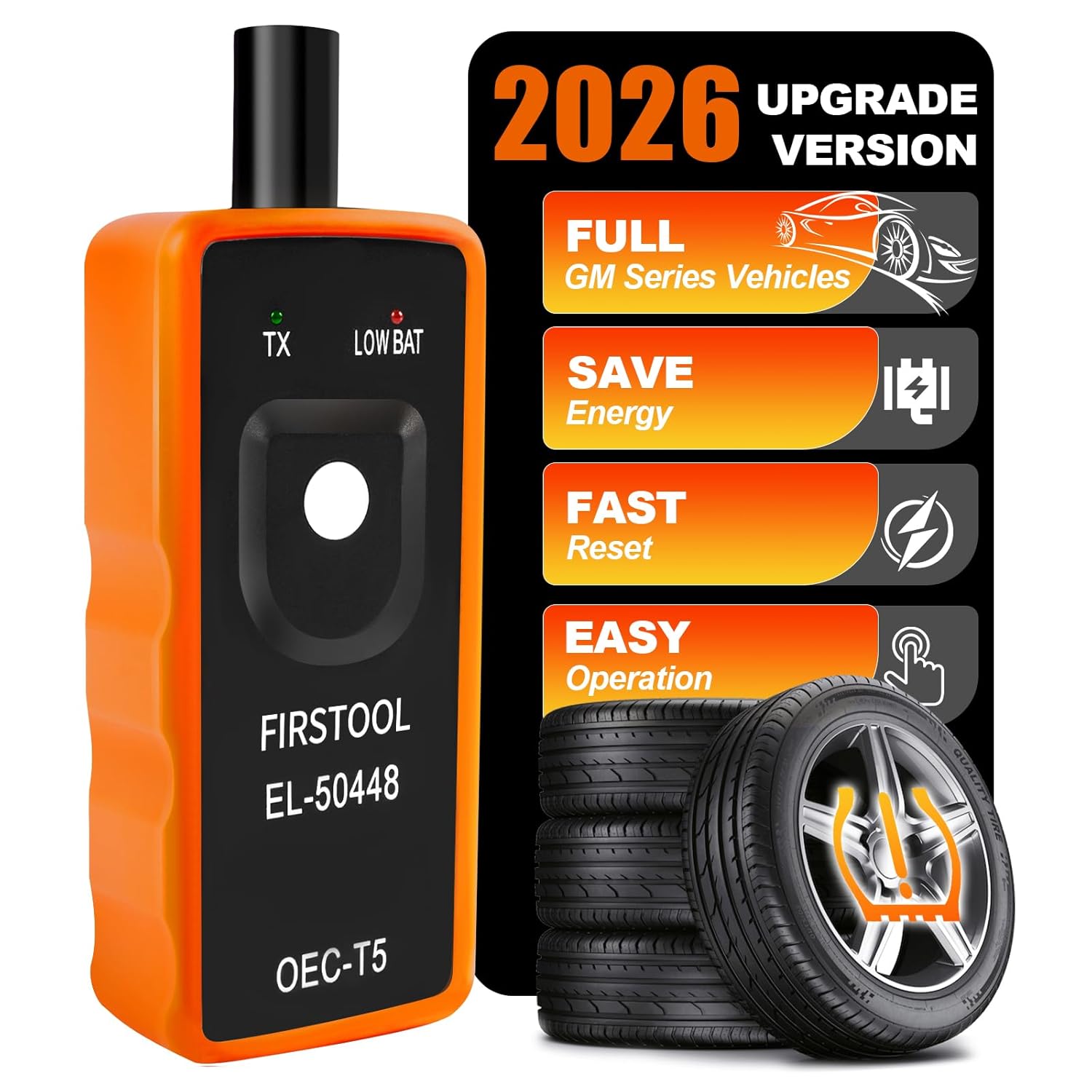
This TPMS relearn tool helps you quickly activate, match, and reset GM tire pressure sensors to keep the vehicle monitoring system working properly. It clears tire pressure alarms and dashboard warning lights after sensor replacement or tire rotation, and supports learning for common 315/433 MHz TPMS sensors. Designed for simple one-button operation, it can help you avoid unnecessary trips to repair shops.
Basic Electrical Checks With a Multimeter
A digital multimeter can help you measure voltage, resistance, continuity, and—when used correctly—current. However, the test method matters just as much as the number on the display.
- Inspect first. Look for loose battery terminals, corrosion, damaged insulation, broken connectors, loose grounds, and obvious heat damage.
- Check battery voltage under the correct conditions. A conventional fully charged 12-V battery may be around 12.6 V open circuit, but follow the correct procedure for the battery and vehicle.
- Check the charging system. On a conventional system, a general test may show roughly 13–15 V while running, but vehicle-specific specifications take priority.
- Test voltage drop with the circuit operating. Excess resistance is often easier to find when current is actually flowing through the suspect cable or connection.
- Use the wiring diagram. Verify the correct fuse, relay, power feed, connector terminal, control signal, and ground for the affected circuit.
Warning: Never place a multimeter set to its current/amp mode directly across the battery terminals. That can create a very high-current short through the meter. Follow the meter manufacturer’s instructions and the vehicle service procedure.
[Products Worth Considering]

The Big Rig Defense Tire Thumper is a truck tire pressure checker that lets you quickly check multiple tires by giving them a firm whack. Listen for a reassuring thump and feel the stick bounce when a tire is fully inflated, helping you get back on the road safely. It features a comfortable, glove-friendly handle and a secure wrist strap for confident use on busy routes.
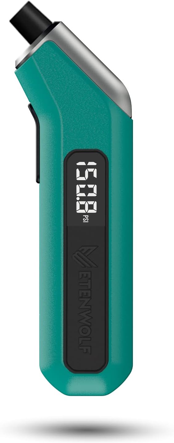
ETENWOLF T300 is a calibrated digital tire pressure gauge designed for reliable readings across low and high pressure ranges. It includes thermal compensation for stable performance in extreme cold or heat, an LED light for visibility, and an auto shut-off to help preserve battery life. Ideal for pickups, RVs, and heavy-duty vehicles, it delivers accurate PSI measurements with sturdy durability.

This 1/2-inch drive breaker bar delivers powerful leverage for loosening and tightening stubborn lug nuts and automotive fasteners. The 180-degree flex head helps you reach tight spaces at the angle you need, making tire and brake jobs easier. A spring-loaded ball detent design holds 1/2-inch sockets securely while the chrome-moly head provides durable strength for everyday use.
12-Volt and 48-Volt Electrical Systems
The familiar 12-volt electrical system is still widely used for lighting, control modules, infotainment, and many other vehicle functions. However, some modern mild-hybrid vehicles add a 48-volt system alongside the 12-V network.
For example, Volvo documents mild-hybrid vehicles with a primary 12-V electrical system plus a 48-V support system. The 48-V battery can support functions such as engine starting and regenerative energy recovery, depending on the vehicle. You can see the manufacturer’s explanation in Volvo’s power-supply documentation.
A 48-V mild-hybrid architecture may use a starter-generator and a DC/DC converter to connect the 48-V and 12-V sides of the vehicle. This means the traditional description of “battery plus alternator equals 14 volts” no longer explains every modern vehicle.
Warning: Do not treat a 48-V mild-hybrid battery or a hybrid/EV high-voltage system like an ordinary 12-V battery. Manufacturer instructions may prohibit owner servicing, probing, disconnecting, or jump-starting through those components. Hybrid and electric vehicles can also contain much higher-voltage traction systems that require specialized training and safety procedures.
Electrical Safety Basics
- Follow the vehicle manufacturer’s repair information before disconnecting a battery or electrical component.
- Keep tools and jewelry from bridging battery terminals or live connections.
- Keep hands, clothing, and test leads away from belts, fans, pulleys, and other moving parts when the engine is running.
- Do not bypass a fuse or replace it with a higher rating unless the manufacturer specifically calls for that rating.
- Use caution around airbag/SRS circuits. Do not probe or modify them without the correct service procedure.
- Do not open, disconnect, or probe 48-V or high-voltage hybrid/EV components unless the manufacturer explicitly provides a procedure you are qualified to perform.
Frequently Asked Questions
How Does a Car’s Electrical System Work?
In a conventional car, the battery stores electrical energy and supplies the starter and other circuits when needed. After the engine starts, the alternator supplies electrical power and recharges the battery. Fuses, relays, wiring, switches, grounds, sensors, and electronic modules distribute and control that power.
How to Learn Car Wiring for Beginners?
Start with voltage, current, resistance, Ohm’s Law, series and parallel circuits, fuses, relays, and grounds. Then learn how to read your vehicle’s wiring diagram and use a digital multimeter safely. Practice by tracing one simple circuit—such as a lamp—from the power source through the fuse and switch to the load and ground.
What Is the Most Common Electrical Problem in a Car?
There is no single fault that is guaranteed to be the most common on every vehicle. Battery, terminal, cable, and ground problems are common causes of starting complaints. Blown fuses, charging-system problems, damaged wiring, failed relays, switches, sensors, motors, and electronic modules can also cause electrical symptoms.
What Are the Five Parts of the Automotive Electrical System?
There is no universal five-part definition. For basic study, the battery, starting system, charging system, wiring/grounds, and circuit-protection/control devices are useful major groups. Modern vehicles also contain sensors, control modules, communications networks, motors, converters, and many other electrical loads.
What Voltage Should a Car Battery Read?
A fully charged conventional 12-V lead-acid battery may measure around 12.6 V open circuit when tested correctly. While a conventional charging system operates, a general diagnostic range may be around 13–15 V. These are guides rather than universal specifications, so check the procedure for your battery and vehicle.
Why Does a Car Fuse Keep Blowing?
A fuse that repeatedly opens can indicate excessive current caused by a short circuit, damaged wiring, an overloaded circuit, a failed component, or incorrect aftermarket wiring. Replace it only with the specified fuse type and rating, then diagnose the reason it failed.
Conclusion
Your car’s electrical system is a network rather than a single battery-and-alternator circuit. The battery supplies stored energy, the starter uses high current to crank a conventional engine, and the charging system restores electrical energy after startup. Wiring, grounds, fuses, relays, switches, sensors, modules, and loads then distribute and control that power.
Understanding voltage, current, resistance, polarity, series circuits, parallel circuits, and voltage drop gives you a much better foundation for troubleshooting. Start with visual checks and the correct wiring diagram, test circuits under the right conditions, and use manufacturer specifications instead of assuming every vehicle should produce the same voltage.
Modern vehicles also make electrical safety more important. Some mild hybrids combine 12-V and 48-V systems, while hybrids and EVs can contain much higher-voltage traction circuits. Treat those systems according to the manufacturer’s service and safety instructions.
Sources
- DENSO — Charging System Troubleshooting — charging voltage, wiring inspection, voltage-drop testing, and vehicle-specific specifications.
- DENSO — Battery Visual Inspection & Performance Testing for Starters & Alternators — battery open-circuit voltage, cables, grounds, and battery testing.
- National Institute of Standards and Technology — Ampere: The Present — Ohm’s Law and the relationship between current, voltage, and resistance.
- Eaton — Fuse Technology — overcurrent, overload, short-circuit, and fuse operation principles.
- TE Connectivity — Automotive Relays — relay operating principles and automotive relay configurations.
- Volvo Cars — Power Supply — 12-V and 48-V mild-hybrid electrical systems and 48-V safety guidance.
